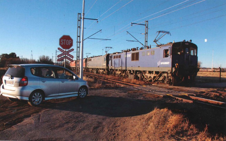
Railway level crossings have since they were first built, been hazardous, and have claimed the lives of many who misjudged the speed of an approaching train. Now, in an attempt to improve safety at level crossings, a Croatian company, Altpro, has developed an advanced electronic level crossing safety system that has been extensively tested and certified for CENELEC SIL (Safety Integrity Level) by TÜV Rheinland.
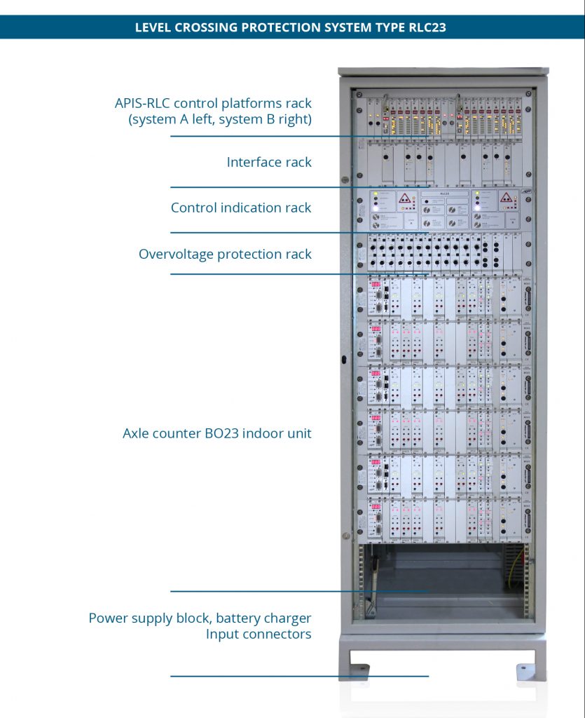
Named the RLC23 level crossing control, it uses the Altpro BO23 axle counter system (which has its own TÜV Rheinland certification for SIL4 safety level) for the detection of train movement. This is used with the APIS-RLC microprocessor control platform, both of which are mounted in the RLC23 control cabinet.
The APIS—RLC Control main microprocessor control unit is composed of two control platforms (A on the left and B on the right) with distributed control modules for controlling respective groups of external devices. Due to safety requirements, this system has been duplicated. The B023 UNUR rack—axle counting evaluator can control up to eight counting points distributed over six sections
The equipment layout in the cabinet can vary depending on the number of tracks, number of road-side signals/lights and railway signalling requirements. The main functions APIS—RLC control system comprises two independent and separate control platforms (A & B) and operates in a basic configuration on a 2-out- of—2 voting principle. By duplicating certain executive modules in both control systems, 2-out-of-3 voting systems can be achieved, further enhancing level crossing availability.
Each platform:
- Controls all roadside light signals (depending on the version) and all sound signals/bells, that are initiated by a train or by manual
- Monitors and controls the track-side driver’s white or yellow light signals and also monitors their current
- Controls the operation of the booms as initiated by a train or manually), and also monitors the integrity of the boom (for instance detecting if it is broken). Optionally, it can control a flashing light at the tip of the
- Can monitor and control the operation of the road-side sound equipment/bells.
- Receives information from the Bo23 axle counter track— side sensors about both occupancy/clearance of the track sections and train
- Continuously communicates with the respective platforms in the remote monitoring stations
- Each platform controls indication/control board elements and receives manual commands governing functions such as on and off switching, forced manual restoring, testing/ disturbance simulation among
- Monitors the two battery power supplies, and AC power as well as correct functioning of the battery
- Records and retains data in non-volatile memory (safe in case of power failure). This records information such as date/time of last 10,000 trains passed, number of axles, occupancy, travel direction and speed, errors/faults/disturbances. This information is used for evaluation or investigation of the past

The control system can be configured for additional functions that may be necessary for a particular application and to comply with various operational regulations.
The RLC23 system can control up to four tracI‹s with one control system/evaluator. One Altpro Bo23 axle counter system can perform complete train detection on two tracks of an open line.
When track-side railway signal lights that inform the train driver about level crossing conditions are installed, this system controls their on and off cycles and continuously monitors the current reaching each filament. When installed, the control system can also monitor or control the power supply to the crossing warning bells.
In terms of booms, two pairs can be controlled. An additional pair can be added only if they operate simultaneously with one of the first two booms, which will be operated at the same time. The lifting and lowering time of the booms is programmable to suit the site requirements.
Should a boom be damaged, level crossing control will alert the operator.
Regarding roadside lights and signals, authorities in various parts of the world have their own site requirements for the shape and number of signals/lights. This equipment may be of various types and can be made by any manufacturer.
The RLC23 level control system is immune to traction return- current on the rails. It has a three—stage lightning/over—voltage protection, is EMC—immune according to the EN 50121-4 standard, uses safety relays with forcibly guided contacts according to the EN 50205 standard and is easily configurable by using a Windows PC.
The APIS-RLC23 control system continuously receives information about rail occupancy/train position and direction over a counting point from the B023 axle counter system. Any train movement will automatically lower or lift the boom depending on the train position.
A high level of configurability is possible to suit differing local level crossing requirements. For example, in the case of a train stopping between the switch-ON counting point and the road, the level crossing can be configured so that it automatically switches the barrier drive on and off at required/preset times and for/the specified site “HALT” conditions.
Additional axle counters may be needed to suit specific operators’ requirements (e.g. when points machines are involved). Similarly, many configuration choices are possible to suit the control/ interface of the train driver’s signalling (on the track) as well as the remote monitoring/control requirements of the operator.
For each level crossing, it is vital that the operator is in possession of detailed drawings applicable to each site, together with specific listings of the operational requirements for both track-side and roadside equipment. All such information must be discussed, fully understood and accepted by all parties involved in the implementation of level crossing protection. Without this indispensable interaction, the necessary degree of safety in the level crossing control system may not be achieved.
Article published in Railways Africa Issue 4 // 2014


